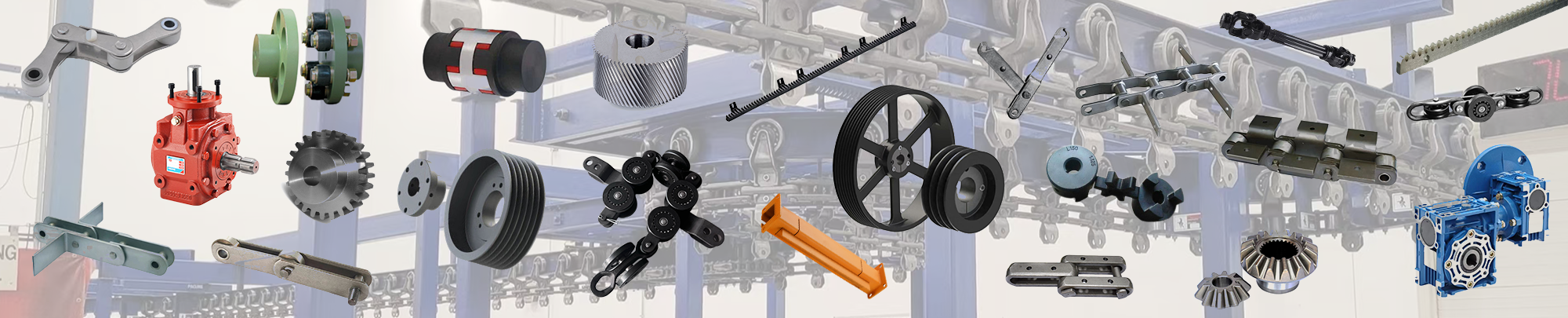
Product Specification
|
Project
Type
|
XT80
|
XT100
|
XT160
|
|
|
Chain link data(mm)
|
80
|
100
|
160
|
|
Chain weight(N/m)
|
38
|
47
|
90
|
|
Single point lifting weight (KN)
|
1.25
|
2.5
|
5
|
|
Allowable tension of chain (KN)
|
10
|
12.5
|
25
|
|
Chain breaking force (KN)
|
≥110
|
≥220
|
≥400
|
|
Track specifications
|
Ordinary I-beam 8# 、10#
|
Ordinary I-beam 12# 、14#
|
Ordinary I-beam 14# 、16#
|
|
Track specification weight (N/m)
|
89.6 、112
|
140 、169
|
169 、205
|
|
Running speed (m/min)
|
0~1.2 、2.1 、3.3 、4.8 、8.3
|
0~1.1 、2.0 、3.2 、4.5 、7.2
|
0~13 、2.0 、3.2 、4.5 、6.0
|
|
Working temperature (℃)
|
-20~250
|
-20~250
|
-20~250
|
|
Conveyor power( KW)
|
1.2 、2.2
|
1.5 、2.2
|
2.2 、3.4
|
Product composition
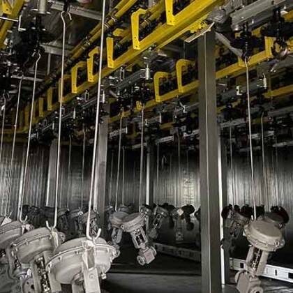
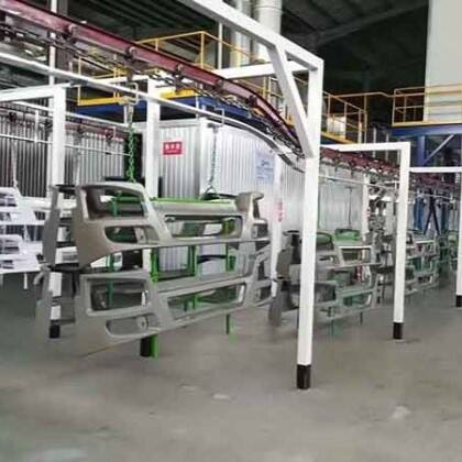
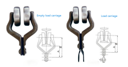
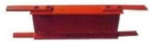
Trolley
The main function of the die-forged slide is to bear the weight of objects, spreaders and chains. It also bears the resultant force of the chain tension in the vertical bending section, and can ensure that the chain runs according to the track line. When the distance between two loaded carriages in the line exceeds 800~900mm, a load carriage can be added in the middle.
|
Project
Type
|
A
|
B
|
C
|
D
|
E
|
|
XT80
|
63.5
|
100
|
16
|
φ12
|
66
|
|
XT100
|
82
|
131.1
|
20
|
φ12
|
74
|
|
XT160
|
102
|
170.8
|
25
|
φ20
|
109
|
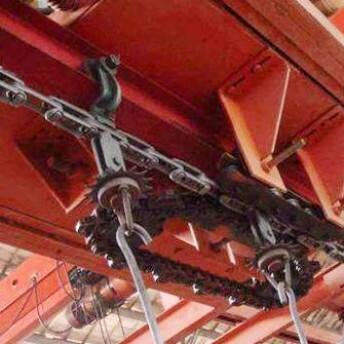
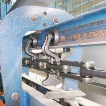
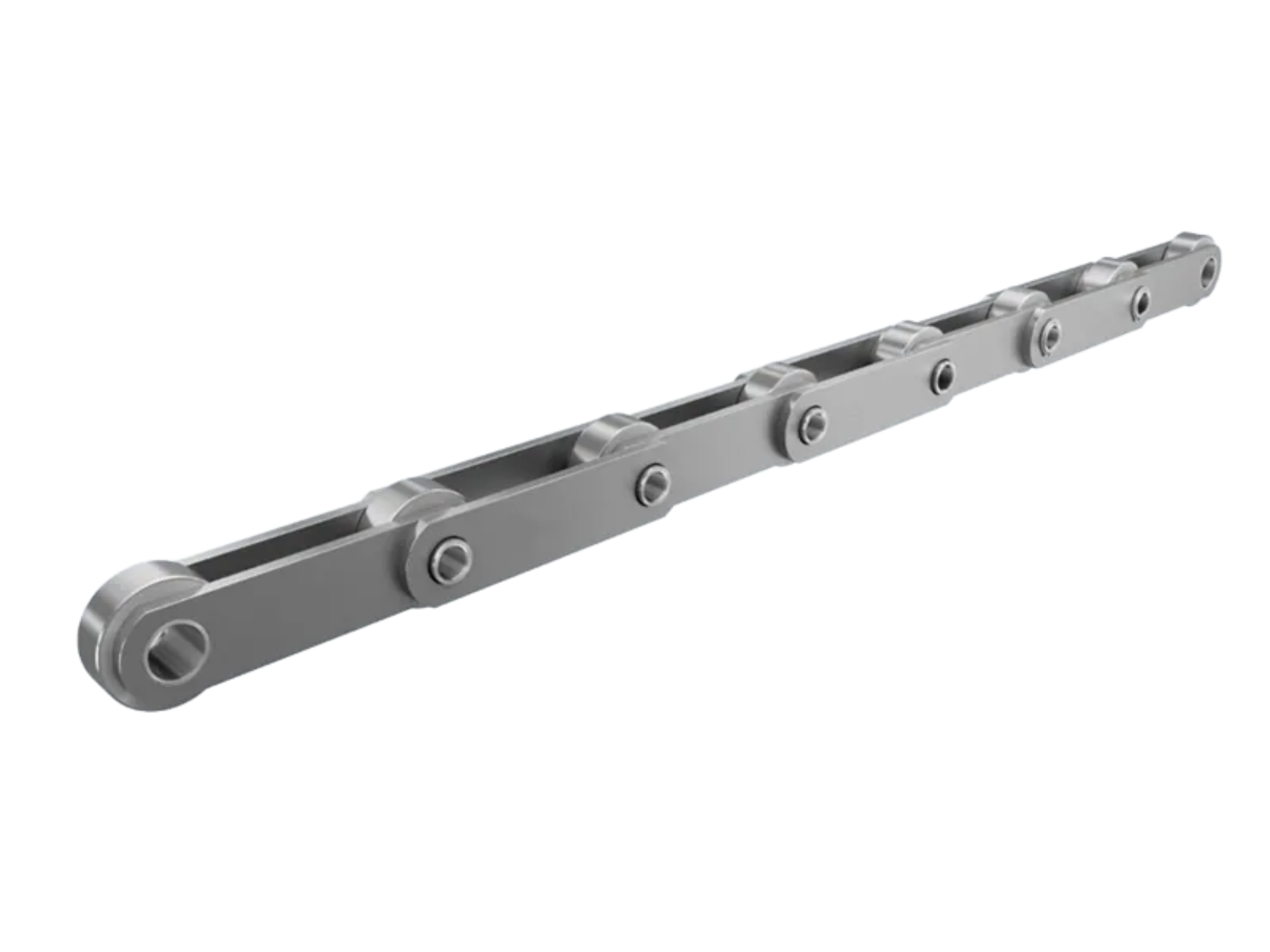
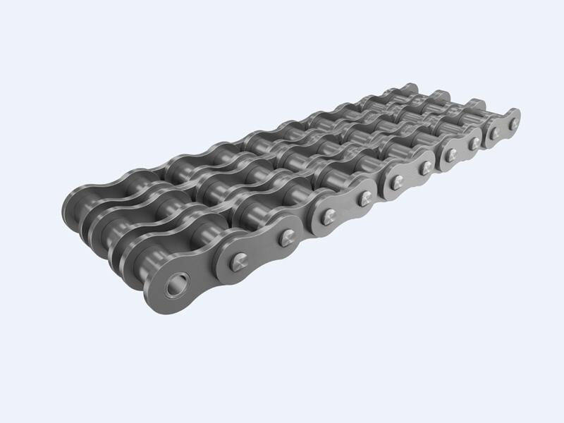
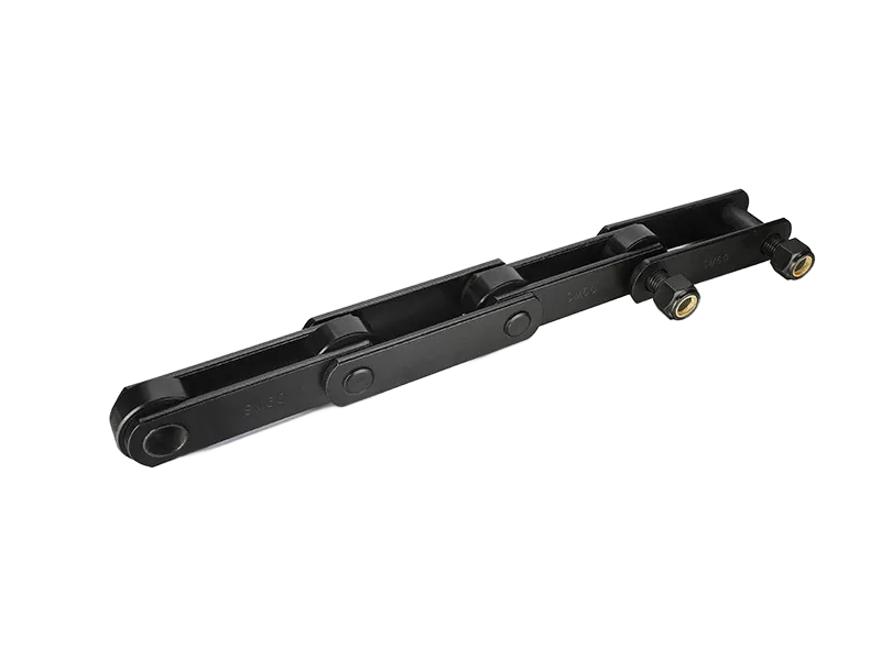
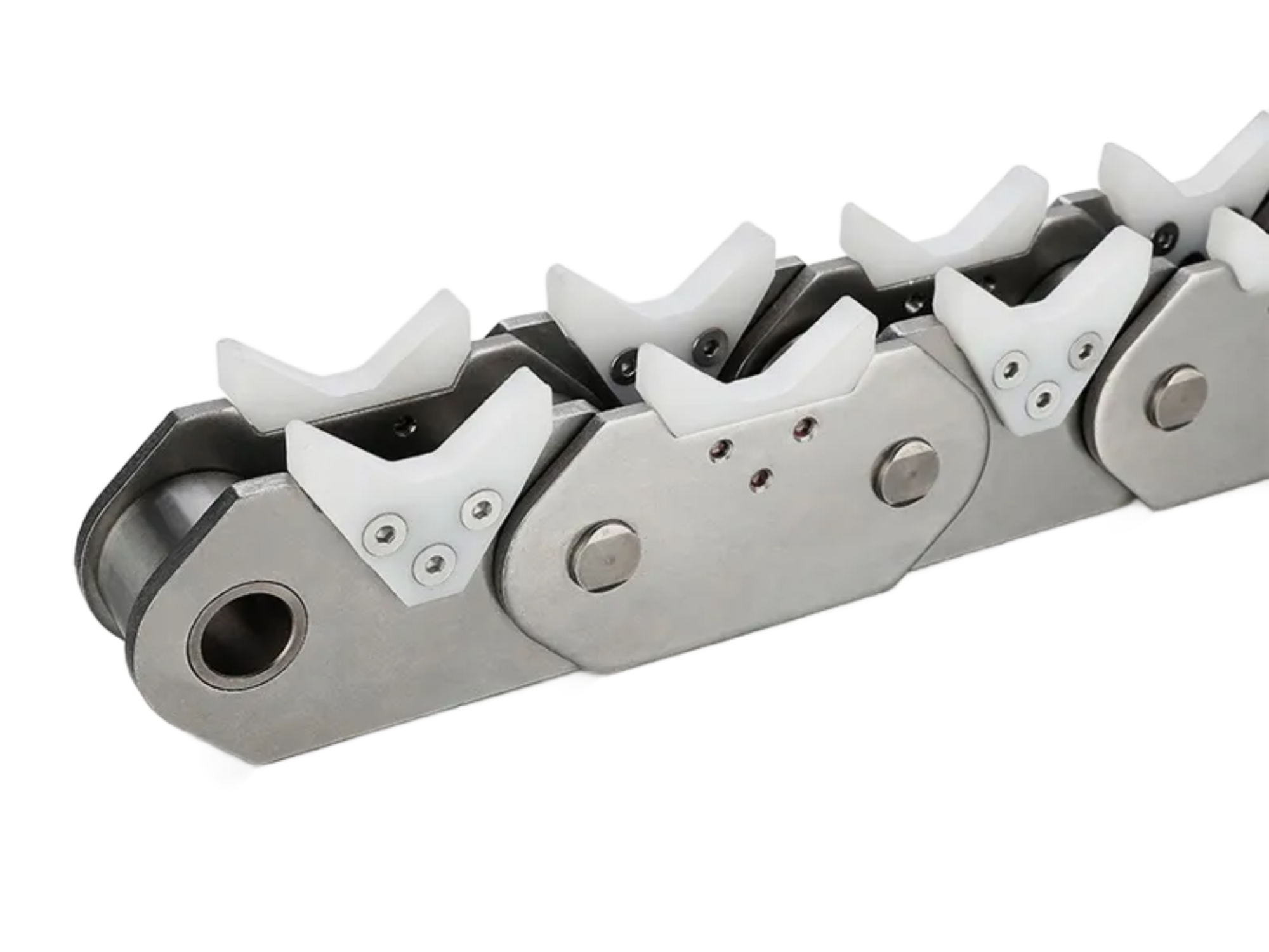
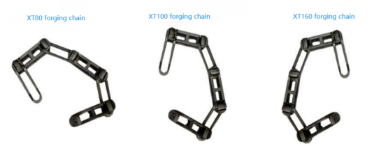
XT Forged chain
The chain is the traction component of the conveyor. There are two types of chains for XT80, XT100, it can rotate arbitrarily in the horizontal and vertical directions.
|
Project
Type
|
P
|
C
|
a
|
|
XT80
|
80(76.2)
|
1.5-2.5
|
≥9°
|
|
XT100
|
100
|
1.5-2.5
|
≥9°
|
|
XT160
|
160
|
2-4
|
≥6°
|
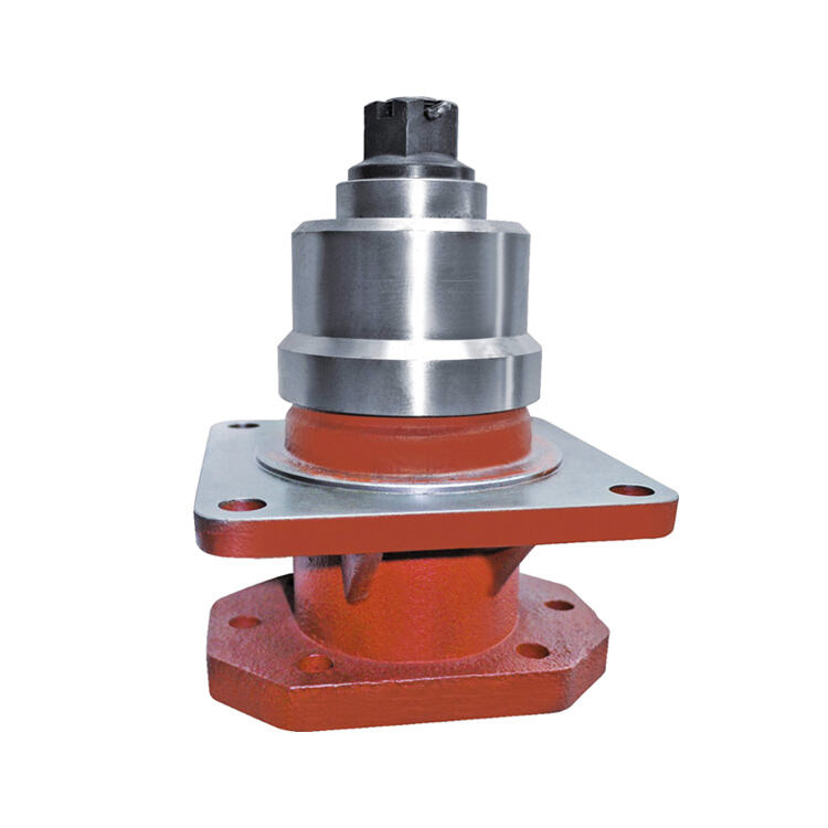
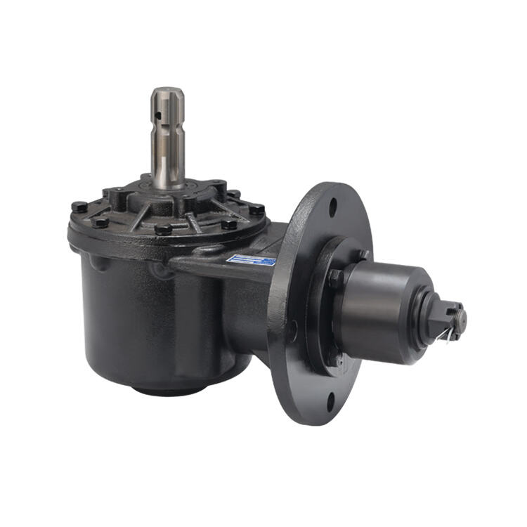
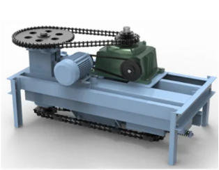
Driving device
The device adopts a direct-coupled cycloidal pinwheel reducer transmission structure, which has high transmission efficiency and reliable movement. The drive frame is divided into inner and outer frames. When unexpected situations such as resistance overload occurs, the inner frame moves relative to the outer frame, and the travel switch operates for electrical protection. The transmission device should be arranged high on the line with greater tension, and the convenience of hanging and maintenance should also be considered.
|
Project
Type
|
A1
|
A
|
B1
|
B
|
L
|
|
XT80
|
1586
|
1640
|
750
|
1000
|
≤1472
|
|
XT100
|
1586
|
1640
|
750
|
1000
|
≤1472
|
|
XT160
|
1771
|
1825
|
820
|
1000
|
≤1560
|
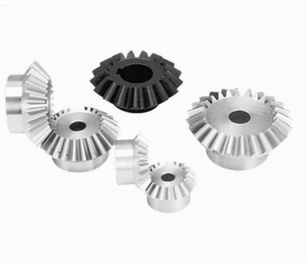
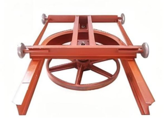
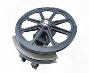
Angle drive
The device uses a planetary reducer belt transmission. The standard drive wheel has 10 teeth. For special needs, a 13-tooth drive wheel can be provided under the premise of ensuring reducer strength. Speed range: 0.5 - 10m/min for smooth and stable line transportation. Recommended linear speed within allowable conveying volume is 2 - 6 m/min for service life. Considering possible damage from overload accidents, it's equipped with a safety pin. Once overloaded, the pin cuts off immediately to protect the drive.
|
project
Type
|
L
|
A1
|
A
|
B1
|
B
|
D
|
|
XT80
|
757
|
1300
|
1360
|
640
|
700
|
φ666
|
|
XT100
|
757
|
1340
|
1400
|
780
|
840
|
φ652
|
|
XT160
|
895
|
1460
|
1500
|
785
|
850
|
φ826.5
|
Tightening Device
The tensioning device ensures chain tension, compensates for installation errors and chain elongation due to tension, wear and temperature differences. It ensures initial tension at the winding point of the drive device and eliminates negative devices in the entire line. For XT80, XT100 and others, the tensioner should be placed in a place with smaller tension, usually at a lower location near the back of the transmission device. There should be no large load descending slope near the tensioner.
|
Project
Type
|
XT80、XT76.2
|
XT100
|
XT160
|
|
R
|
305
|
381
|
533
|
610
|
317
|
413
|
508
|
637
|
404
|
508
|
660
|
815
|
|
D
|
φ580
|
φ732
|
φ1036
|
φ1190
|
φ606
|
φ797
|
φ986
|
φ1240
|
φ770
|
φ970
|
φ1275
|
φ1581
|
|
A
|
1235
|
1315
|
1470
|
1590
|
1245
|
1345
|
1445
|
1615
|
1495
|
1600
|
1760
|
1910
|
|
B
|
630
|
650
|
700
|
800
|
630
|
680
|
680
|
800
|
850
|
850
|
850
|
850
|
|
C
|
900
|
1100
|
1300
|
1650
|
900
|
1100
|
1300
|
1650
|
1100
|
1300
|
1620
|
1930
|
|
E
|
63.5
|
82
|
102
|
|
F
|
280
|
280
|
300
|
|
Tighten the itinerary
|
250
|
250
|
400
|
Return idler horizontal curve
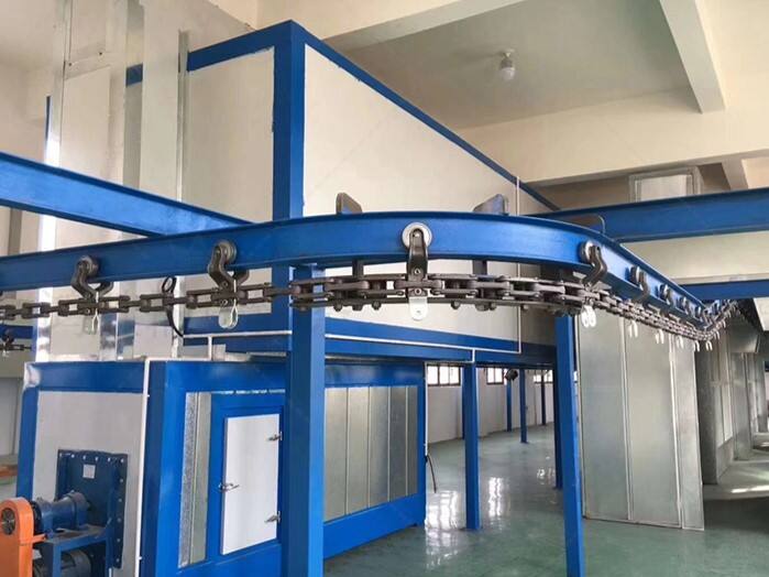
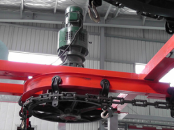
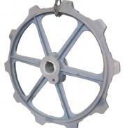
The slewing device is a horizontal redirection device that guides the chain and the carriage to turn smoothly along the track. It is installed on the horizontal turning rail section of the line. The slewing device can be divided into three structures: sprocket rotation, smooth wheel rotation, and roller row rotation.
|
Project
Type
|
A
|
B
|
Turning radius(R)
|
D
|
C
|
|
XT80
|
180
|
250
|
305
381
533
610
|
φ580
φ732
φ1036
φ1190
|
63.5
|
|
|
|
|
XT100
|
180
|
250
|
317
413
508
637
|
φ606
φ797
φ986
φ1240
|
822
|
|
|
|
|
XT160
|
200
|
350
|
404
508
660
815
|
φ770
φ970
φ1275
φ1581
|
102
|
|
|
Project
Type
|
XT80、XT100
|
XT160
|
|
Turning radius(R)
|
1000 1200
|
1400
|
2000 2500 3000
|
|
n
|
82.8 111.3
|
117.8
|
166.8 157.8 152.4
|
|
a
|
41.4 50.2
|
58.9
|
200 200 200
|
|
α
|
15°、30°、45°、60°、75°
|
|
Project
Type
|
XT80、XT100
|
XT160
|
|
Turning radius(R)
|
1000
|
1200
|
1400
|
2000
|
2500
|
3000
|
|
n
|
82.8
|
111.3
|
117.8
|
166.8
|
157.8
|
152.4
|
|
a
|
41.4
|
50.2
|
58.9
|
200
|
200
|
200
|
|
α
|
180°
|
180°
|
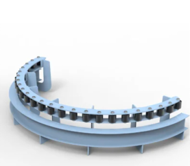
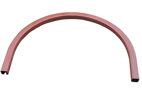
Horizontal curves
It is used for horizontal turns when the conveyor chain travels. The standard radius is R305mm to R815mm with an angle of 180° . It can be cut to any degree according to the installation site conditions. Horizontal elbows can also be customized and processed according to customer needs.
|
Project
Type
|
XT80
|
XT100
|
XT160
|
|
R
|
305、381、533、610
|
317、413、508、637
|
404、508、660、815
|
|
a
|
30°、45°、60°、75°、90°、180°
|
|
Specification for I-beam track
|
8#
|
10#
|
12#
|
14#
|
14#
|
16#
|
|
L
|
80
|
100
|
120
|
140
|
140
|
160
|
|
B
|
62
|
68
|
74
|
80
|
80
|
88
|
|
m
|
160
|
160
|
160
|
160
|
160
|
180
|
Activity track
Furnace track hanger clamp
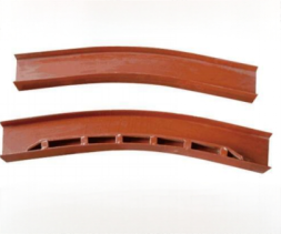
XT Vertical curve
It is used at the ascending and descending points of the conveyor chain. It can be cut at any angle according to the installation site conditions, but the angle should not be greater than 45 °. However, the influence of the distance between the two spreaders connected to the ascending and descending points must also be considered.
|
Project
Type
|
Track
specifications
|
m
|
R
|
α
|
|
|
XT80
|
8#
|
160
|
1500 2000 2500
|
15°
|
|
10#
|
30°
|
|
XT100
|
12#
|
160
|
2000 2500 3150 4000 5000
|
30°
|
|
14#
|
45°
|
|
XT160
|
14#
|
160
|
2000 2500 3000 3500 4000 4500 5000
|
15°
|
|
35°
|
|
16#
|
180
|
45°
|
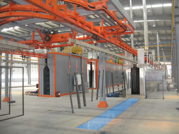
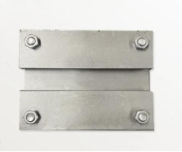
Temperature Expansion Rail
When the running track passes through high temperature sections s uch as baking, temperature expansion joints should be added at both ends of the high-temperature section. One end of the temperature expansion joint should be welded to the track, and the other end should be a sliding sleeve with the other track. Maintain an appropriate gap between the two rails to compensate for thermal deformation.
 EN
EN
 AR
AR
 FI
FI
 NL
NL
 DA
DA
 CS
CS
 PT
PT
 PL
PL
 NO
NO
 KO
KO
 JA
JA
 IT
IT
 HI
HI
 EL
EL
 FR
FR
 DE
DE
 RO
RO
 RU
RU
 ES
ES
 SV
SV
 TL
TL
 IW
IW
 ID
ID
 SK
SK
 UK
UK
 VI
VI
 HU
HU
 TH
TH
 FA
FA
 MS
MS
 HA
HA
 KM
KM
 LO
LO
 NE
NE
 PA
PA
 YO
YO
 MY
MY
 KK
KK
 SI
SI
 KY
KY